
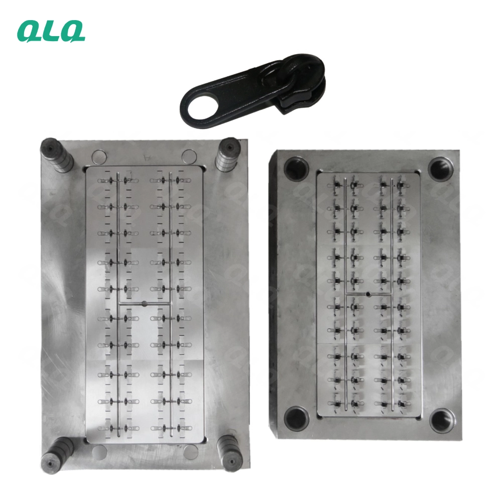
The economics of a POM slider line are decided in the mould. A 16-cavity tool and a 72-cavity tool make the same slider, but one produces a fraction of the other per shot, and the difference in tool cost, cooling design and maintenance is what separates a competitive quote from a losing one.
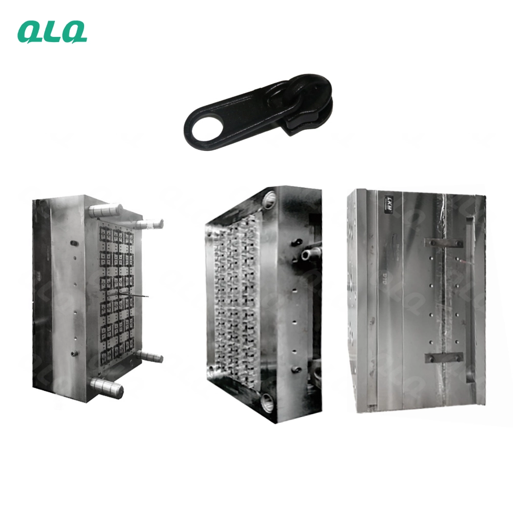
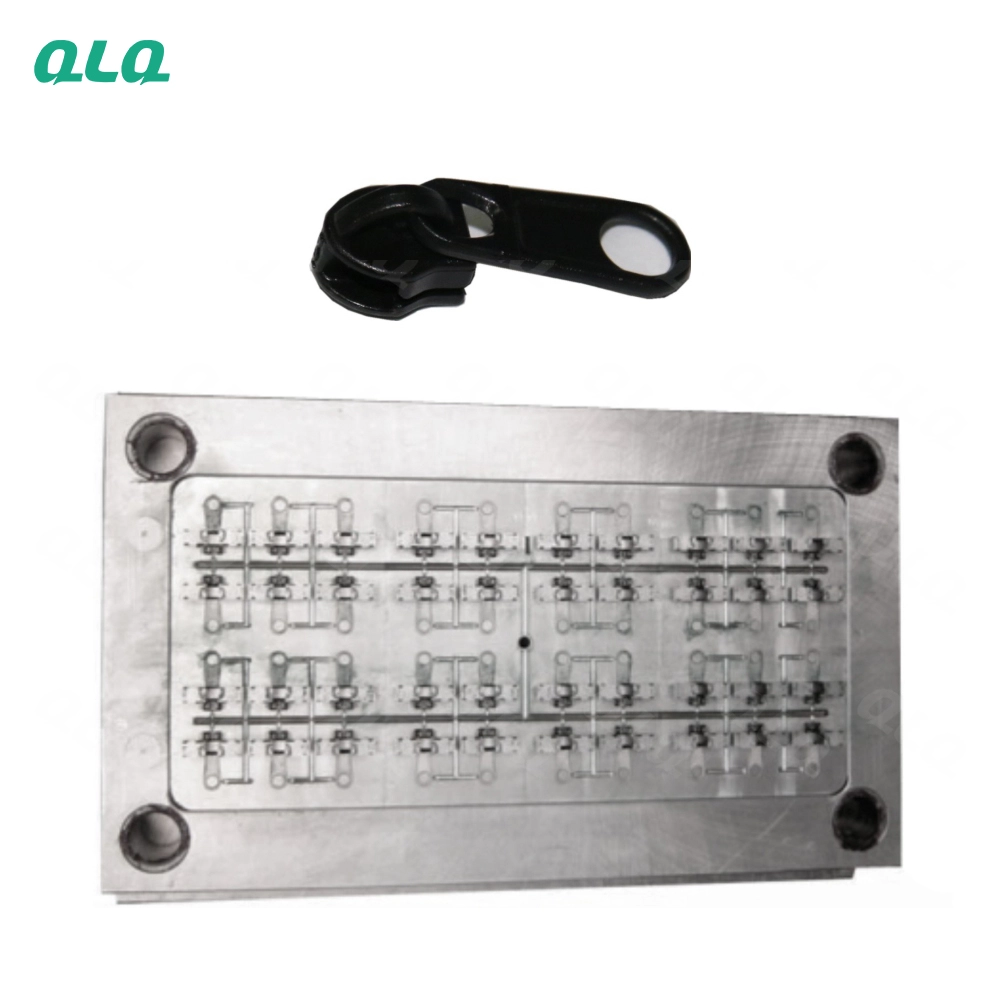
This guide explains how to design or select a POM slider injection mould: cavity counts from 16 to 72, shrinkage compensation for POM at 1.8-2.5%, gate and runner layout, cooling channels, venting, steel selection and expected mould life. It is written for owners and process engineers comparing mould options for slider production.
Common Mistakes and How to Avoid Them
The pitfalls that show up most often in real projects, with the cause and the practical fix.
| Mistake | Why It Happens | Practical Fix |
|---|---|---|
| 1. Choosing cavities by habit, not by order size | A 72-cavity tool is wasted on small orders; a 16-cavity tool cannot win large quotes | Match cavity count to forecast volume, cycle time and machine capacity |
| 2. Ignoring POM shrinkage | Parts come out undersized and cannot hold the puller or fit the chain | Compensate the cavity for 1.8-2.5% shrinkage before cutting steel |
| 3. Unbalanced runner lengths | Some cavities fill late, giving short shots and flash on one side | Design balanced runners so all cavities fill at the same time |
| 4. Gate too small or too thin | Slow fill, weld lines and high injection pressure | Size the gate for the slider wall thickness and fill time |
| 5. No cooling analysis | Uneven cooling warps thin slider bodies | Balance cooling channels and keep mould temperature at 60-90C |
| 6. Poor venting | Bubbles and burn marks at the end of fill | Add vents at weld-line and last-fill positions |
| 7. Cheap steel for high volume | Early wear at gates and parting lines increases flash | Choose P20 for prototyping, S136/H13 for high-volume tools |
| 8. No spare core inserts | A damaged cavity stops the whole machine | Keep spare inserts for high-wear cavities |
| 9. Skipping trial shots before production | Design errors run into production | Run a full mould trial and dimension check before mass production |
| 10. No maintenance schedule | Flash and surface defects grow slowly | Clean, inspect and polish the mould on a fixed schedule |
Best Practices That Hold Up in Production
The operating disciplines that separate a reliable line from a reactive one.
- Match cavity count to your real order forecast and machine capacity
- Compensate cavity dimensions for 1.8-2.5% POM shrinkage
- Design balanced runners and gates for equal fill
- Analyze cooling early; target 60-90C mould temperature with balanced channels
- Vent at weld lines and last-fill areas
- Choose steel by volume: P20 for short runs, S136/H13 for long runs
- Keep spare inserts for the highest-wear cavities
- Trial the mould and measure parts before mass production
Implementation Roadmap
A practical sequence that can be adapted to your own project.
Working Data & Formula Notes
POM slider mould design data
Reference values from QLQ slider mould notes; confirm shrinkage and cavity layout with your mould maker for the exact resin grade.
| Component / Parameter | Working Value / Role | What Changes Mean (annotation) |
|---|---|---|
| Cavity counts in common use | 16 / 20 / 24 / 40 / 48 / 72 | Higher cavities raise output per shot but increase tool cost, cooling demand and setup care |
| POM shrinkage | 1.8-2.5% | If ignored, the molded slider is undersized and fails chain fit or puller retention |
| Mould temperature | 60-90C | Cold steel gives sink marks and unstable dimensions; temperature must be stable across the plate |
| Cooling time | 3-8 seconds per shot | Shorter cooling warps thin sections; longer cooling lowers output |
| Typical injection mould life | 500,000-1,000,000 shots | Life depends on steel, maintenance and resin; gates wear first |
| Mould steel - P20 | Pre-hardened, easy to machine | Good for prototyping and short-to-medium runs |
| Mould steel - S136 / H13 | Corrosion-resistant / hot-work steel | Better for high-volume or colored-slider production |
| Dimension precision | 0.02 mm machining achievable | Precision affects chain fit and consistent slide feel |
Reference Data
Specifications and references cited in this guide. Confirm final parameters with your line supplier.
Cavity configuration versus output character
| 16 cavities | Low tool cost, easy cooling balance | Sampling, small orders, multi-size flexibility |
| 20-24 cavities | Balanced cost and output | Medium orders, single-size focus |
| 40 cavities | Good output for medium-high volume | Standard slider sizes |
| 48 cavities | High output, common production choice | Core sizes with steady demand |
| 72 cavities | Highest output per shot | Very large orders and dedicated sizes |
Mould steel selection for POM slider tools
| P20 | Pre-hardened mould steel | Prototyping and short runs |
| S136 | Stainless mould steel, corrosion resistant | Color-sensitive and long-run tools |
| H13 | Hot-work steel, tough | High-cycle tools and thin sections |
| Insert steels | Hardened grades for gates and wear points | High-wear cavity inserts |
Mould trial checklist
| Fill balance | All cavities fill completely without short shots | Check first and last cavity parts |
| Flash check | No flash at parting line | Check clamp force and mould fit |
| Sink marks | No sink on thick sections | Adjust holding pressure and time |
| Dimension | Within drawing tolerance after shrinkage | Measure across cavities |
| Cooling | Stable 60-90C after 1 hour running | Record temperature distribution |
| Ejection | Clean release without marks | Check ejector pins and draft |
Implementation Cases
Case 1 - moving from 16 to 48 cavities for a core size
Situation. A slider producer in India was running a core #5 POM slider on a 16-cavity tool and could not meet delivery for a growing export order.
Approach. The forecast justified a dedicated 48-cavity tool with balanced hot runners and cooled cores. The mould was compensated for 2.2% shrinkage and trialled with the exact resin grade before production.
Outcome. Output per shot tripled, cycle time stayed stable, and the factory could accept the larger order without adding a second machine immediately.
Case 2 - flexible 24-cavity tool for multiple sizes
Situation. A factory in Poland produced several small POM slider sizes and could not justify a dedicated tool per size.
Approach. They chose a 24-cavity tool with interchangeable inserts so two sizes shared the same frame, and set a 45-minute changeover routine with first-piece checks.
Outcome. The factory reduced mould capital cost while keeping reasonable output, and changeover time between sizes became predictable.
Frequently Asked Questions
How many cavities should my POM slider mould have?
Match the cavity count to your order forecast. A 16-24 cavity tool suits sampling and flexible small orders; 40-48 cavities suit steady core sizes; 72 cavities suits very large dedicated orders. Higher cavities raise tool cost and cooling complexity.
Why do POM sliders come out undersized?
POM shrinks about 1.8-2.5% as it cools. The mould cavity must be designed larger than the finished part to compensate. If the cavity was cut without this allowance, parts will be undersized.
What is the best mould steel for plastic sliders?
P20 is fine for prototyping and short runs. For long-run production, S136 resists corrosion and keeps surfaces clean, and H13 is used where toughness matters. Confirm with your mould maker based on expected shot count.
How long does an injection mould for sliders last?
A well-maintained injection mould can reach 500,000 to 1,000,000 shots. Wear appears first at gates and parting lines, so keep spare inserts for high-wear cavities.
What mould temperature should I use?
The reference range for POM sliders is 60-90C. A stable mould temperature improves fill, surface finish and dimensional stability.
Does a higher cavity count always lower cost per piece?
Only when orders are large enough to keep the tool and machine busy. For small orders, a high-cavity tool increases capital and maintenance cost without saving enough per piece.
Why do some cavities fill late on my multi-cavity mould?
Late cavities usually mean unbalanced runners or gates. Balance the flow so all cavities fill at the same time; otherwise you get short shots on one side and flash on the other.
Can one mould make several slider sizes?
Yes, with interchangeable inserts. The frame stays the same and inserts change per size. Changeover takes longer than a single-size tool but saves capital when volumes are small.
What Would You Like to Solve?
Share your slider drawing, sizes and annual forecast, and we can help you choose the cavity configuration, review the shrinkage compensation and cooling design, and plan a mould trial that protects your production schedule.
Published by QLQ - a complete high-quality zipper manufacturing equipment, moulds and materials solution supplier, and the only supplier in China covering the full process chain from raw material through electroplating and painting as one integrated system. Values cited are project references; confirm with your line supplier before specification.