
A zipper factory layout is decided long before the first machine arrives. The same equipment list can produce smoothly in one building and jam constantly in another, and the difference is usually zoning: where the raw material sits, which direction the chain moves, how far the plating and painting areas are from packing, and whether the aisles and utilities were sized at all.
This guide is written for owners and supervisors planning a new nylon, metal or plastic zipper workshop. It converts the questions that come up in real new-plant projects - how much floor area, how much power, which zones, what spacing - into a zone-by-zone layout method that can be used with any building and any equipment supplier.
Common Mistakes and How to Avoid Them
The pitfalls that show up most often in real projects, with the cause and the practical fix.
| Mistake | Why It Happens | Practical Fix |
|---|---|---|
| 1. Designing the layout before the product plan | Machine count and zone sizes depend on product type and daily output | Freeze product mix, sizes and target output first; then size each zone from the machine list |
| 2. Mixing wet and dry processes | Dyeing, plating and painting release moisture, fumes and chemicals near packing and storage | Separate wet zones with walls or clear distance, and keep them downwind of packing |
| 3. Undersized raw material warehouse | Yarn, wire, pellets and chemicals need FIFO storage; no room means blocked aisles | Allocate about 15% of net floor space to raw material and warehouse with FIFO racks |
| 4. Ignoring columns and ceiling height | Machines and racking need clear working height and pillar-free paths | Measure column positions and ceiling height before drawing the layout; plan around pillars |
| 5. No expansion reserve | Growing factories find the building full within two years | Leave 20-30% extra floor space for a second line or future machines |
| 6. Plating or painting area without ventilation plan | Exhaust ducting is expensive to retrofit and hard to move | Mark exhaust and make-up air positions in the layout before pouring floors |
| 7. No wastewater and drainage plan for wet processes | Dyeing, plating and polishing wastewater blocks drains and fails permits | Plan segregation, collection and treatment space in the capex layout |
| 8. Machines packed too tightly | Maintenance teams cannot reach motors, molds and control panels | Keep 3-5 m between major machines and a clear service aisle |
| 9. Power planned from habit instead of the machine list | Voltage or connected load mismatch stops installation | Sum the installed power from the machine list and confirm local voltage (380/220/415/440/480V) |
| 10. No QC and lab corner | Tests are skipped because there is nowhere to run them | Reserve about 10% of space for pull force, cycling, salt spray and color fastness equipment |
Best Practices That Hold Up in Production
The operating disciplines that separate a reliable line from a reactive one.
- Keep material moving one way: raw material in, finished goods out, no backtracking
- Use the 15/55/10/15/5 zone split: warehouse, production, QC, packing, utilities
- Place dyeing, plating and painting on the downwind side with separate exhaust
- Put the QC lab beside the production floor, not in the office building
- Size the compressor room for peak demand plus 20% headroom
- Confirm ceiling height above 4.5 m and floor load for heavy machines
- Plan a dust-free packing and finished-goods zone away from polishing
- Keep a written layout with machine footprints, power points and material-flow arrows
Implementation Roadmap
A practical sequence that can be adapted to your own project.
Working Data & Formula Notes
Zone-by-zone space and utility planning data
Reference values from QLQ new-factory quick tables and real customer projects. Net area excludes warehouse extension, office and dormitory; confirm final numbers with your line supplier.
| Component / Parameter | Working Value / Role | What Changes Mean (annotation) |
|---|---|---|
| Raw material & warehouse share | About 15% of net floor space | Too small means blocked aisles and mixing of batches; FIFO becomes impossible |
| Production zones share | About 55% of net floor space | Over-tight layout raises changeover time and increases cross-contamination between product types |
| QC & lab share | About 10% of net floor space | Skipping it pushes testing to desks or stops testing altogether |
| Packing & finished goods share | About 15% of net floor space | Undersized packing area creates damage and delays at the shipping dock |
| Utilities & treatment share | About 5% of net floor space | Compressor, cooling tower, exhaust and wastewater need defined rooms, not corridors |
| Aisle width | 3-5 m between major machines | Narrow aisles block maintenance and cause safety incidents around moving parts |
| Ceiling height | Above 4.5 m | Lower ceilings restrict racking, ventilation ducting and heavy machine handling |
| Expansion reserve | 20-30% extra floor space | No reserve forces a second building or a painful re-layout within two years |
Reference Data
Specifications and references cited in this guide. Confirm final parameters with your line supplier.
Area, power and staff references by plant type
| Small nylon plant (10,000 pcs/day) | 375 m2 | 120 kW | 25-35 staff | USD 100k-140k equipment |
| Medium nylon plant (50,000 pcs/day) | 850 m2 | 300 kW | 60-90 staff | USD 350k-500k equipment |
| Small plastic plant (10,000 pcs/day) | 225 m2 | 100 kW | 20-30 staff | USD 120k-180k equipment |
| Medium plastic plant (50,000 pcs/day) | 530 m2 | 260 kW | 55-80 staff | USD 400k-600k equipment |
| Small metal plant (10,000 pcs/day) | 280 m2 | 110 kW | 25-35 staff | USD 150k-220k equipment |
| Medium metal plant (50,000 pcs/day) | 650 m2 | 280 kW | 60-90 staff | USD 450k-650k equipment |
| Plating line (basic in-house) | 250-350 m2 | 150 kW | 10-15 staff | USD 110k-210k equipment |
| Small assembly workshop (20,000 pcs/day) | 130 m2 | 15 kW | 15-25 staff | USD 34k-54k equipment |
Machine placement order for one product line
| Nylon line flow | Weaving -> monofilament -> coil forming -> stitching -> ironing -> dyeing -> coding -> winding -> assembly |
| Metal line flow | Wire flattening -> Y-teeth stamping -> tooth fixing -> polishing -> plating -> assembly |
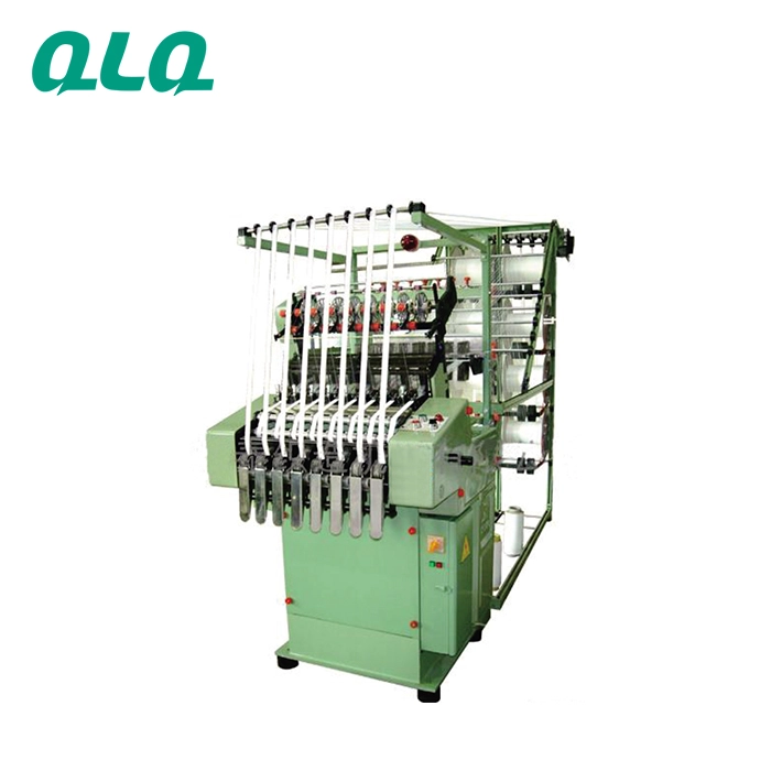
| Plastic line flow | Weaving -> injection molding -> cooling -> trimming -> gapping -> assembly |
| Assembly zone flow | Cutting -> gapping -> slider mounting -> top/bottom stop -> final inspection -> packing |
| Wet process position | Dyeing/plating/painting separated and downwind, with drainage and exhaust |
Implementation Cases
Case 1 - a combined nylon and plastic plant planned around two product lines
Situation. A first-time investor in South Asia wanted to make nylon coil zippers and POM plastic zippers in one rented building of about 1,200 m2, with 10,000 pieces/day per line.
Approach. The layout was drawn as two parallel flows sharing one warehouse and QC lab: nylon line on one side, plastic line on the other, with dyeing and drying separated and a single packing zone at the end. Machine footprints, power points and aisle positions were confirmed before ordering.
Outcome. Both lines were installed without moving walls or re-pouring power, and the QC lab now tests both product types with one set of equipment.
Case 2 - a metal zipper factory adding an in-house plating bay
Situation. A metal zipper maker in South America was outsourcing plating and losing color consistency and delivery control; they wanted to bring a small plating line inside an existing 650 m2 workshop.
Approach. A 250-350 m2 bay was planned downwind of polishing, with segregated drainage, exhaust over tanks, rectifier positions and a basic wastewater treatment corner. Polishing and assembly flows were adjusted so plated chain returns to assembly without crossing the raw material area.
Outcome. Plating color control came back in-house, delivery time dropped, and the environmental consultant confirmed the layout could meet local discharge requirements with minor additions.
Frequently Asked Questions
How much floor area do I need for a new zipper factory?
A small nylon plant for 10,000 pieces/day needs about 375 m2 net; a medium plant for 50,000 pieces/day needs about 850 m2. Plastic and metal plants differ slightly - see the reference table - and warehouse, office and dormitory are extra. Send the workshop dimensions and pillar positions, and a line supplier can draw the layout around them.
How much electrical power should I prepare?
Installed power is roughly 100-140 kW for small nylon/plastic/metal lines, 260-300 kW for medium 50,000 pieces/day lines, and about 150 kW for a basic in-house plating line. Confirm voltage and frequency first: 380V/50Hz, 220V/60Hz, 415V/50Hz, 440V/60Hz or 480V/60Hz are all possible.
Should I plan plating and dyeing in-house or outsource them?
Small factories and first-time owners usually outsource dyeing and plating to specialized suppliers. Medium-to-large factories can build them in-house, but must plan ventilation, drainage and wastewater treatment in the layout and confirm local regulations with an environmental consultant first.
Can you provide a factory layout drawing for our building?
Yes. Send the workshop dimensions, column positions, power distribution, water access and the products you want to make. The line supplier will design the machine arrangement and material flow, then confirm footprints and utilities before you order.
What is the best material flow for a zipper plant?
Keep it one-way: raw material warehouse -> production zones -> QC -> packing -> finished goods. Dyeing, plating and painting should be separated and downwind of packing. Avoid backtracking, because it creates confusion, cross-contamination and waiting time.
How much space should the warehouse take?
About 15% of net floor space for raw material and warehouse, plus a separate finished-goods area in the packing zone. FIFO racking needs defined lanes, and yarn, wire, pellets and chemicals should not be stored together with food or packing materials.
What ceiling height is needed?
Above 4.5 m is the common reference for zipper production floors. It allows racking, ventilation ducting and safe handling of heavy machines. Very low ceilings make exhaust installation difficult for plating and painting areas.
How far apart should machines be?
Keep 3-5 m between major machines for maintenance access, mold changes and safety. Service aisles must reach every motor, mold and control panel; packed layouts save a little floor but cost far more in downtime.
How do I plan for future expansion?
Reserve 20-30% extra floor space and design power and compressed air distribution so a second line can connect without re-pouring. Many customers start with one complete line, stabilize for 3-6 months, then expand with the same layout logic.
What Would You Like to Solve?
Every building is different, and the right layout depends on your product mix, target output, ceiling height, column positions, power and whether dyeing or plating will be in-house. Send us your workshop dimensions and product plan, and we will review the zone map, machine footprints and utility routing before you commit to the line.
Published by QLQ - a complete high-quality zipper manufacturing equipment, moulds and materials solution supplier, and the only supplier in China covering the full process chain from raw material through electroplating and painting as one integrated system. Values cited are project references; confirm with your line supplier before specification.